SYMAP®ECO
SYMAP®ECO is a digital protection relay for low voltage systems. Thanks to its integrated protection functions and its role as a human-machine-interface, it proves to be an efficient and cost-effective solution for generators and emergency power systems. It is equipped with three powerful processors and offers comprehensive protection functions for generators. These can be activated and used simultaneously without restrictions.
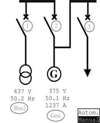
SYMAP®ECO enables the activation of up to three switching elements, including all necessary functions for optimal management such as display, control and blocking.
To ensure maximum flexibility during commissioning and subsequent use, both the digital and analog outputs can be connected to the control elements on the main switchboard via the SYMAP®ECO controller. Additionally, the SYMAP®ECO unit and the main controller can communicate via Modbus RTU protocol. SYMAP®ECO can communicate with various engine control units using different CAN protocols.
SYMAP®ECO features modern cybersecurity functions to protect against unauthorized access and manipulation. Secure communication interfaces and role-based access control ensure reliable and controlled operation.
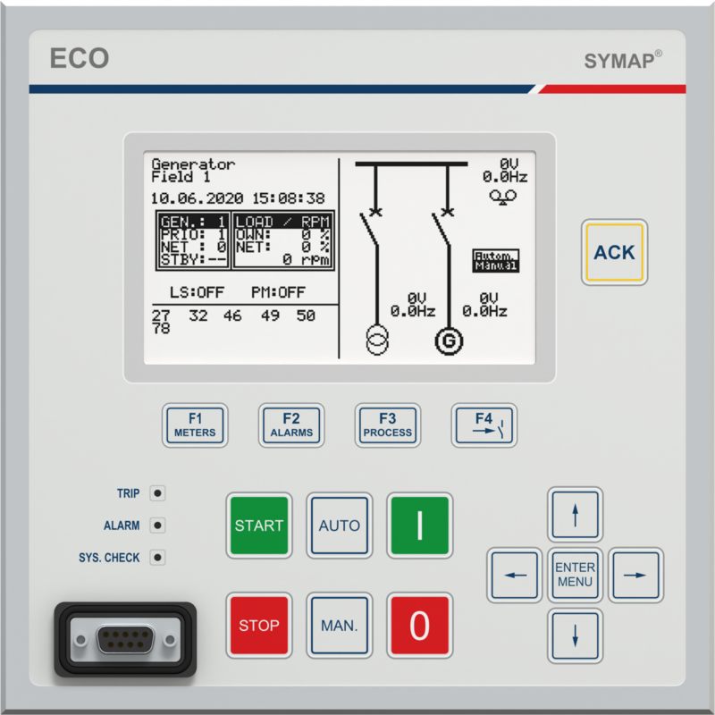
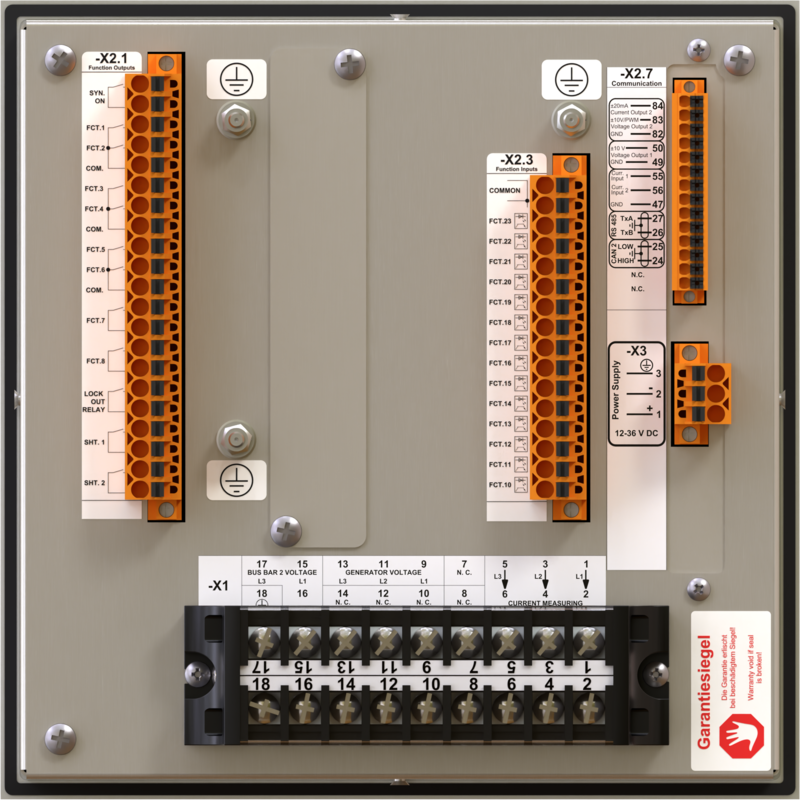
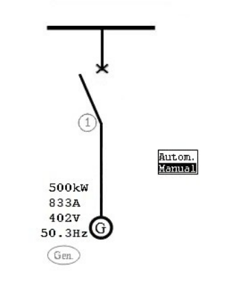
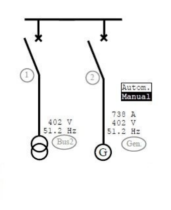
SYMAP®ECO offers three basic templates. The user should select the template according to the topology of the emergency power supply system and the required functionality of the emergency generator.
The functionality of binary inputs, binary outputs and numerous alarm channels is predefined and preprogrammed. Simple configuration of nominal values and basic functions.
Below is a brief overview of all three templates:
Basic 1
- generator circuit breaker
- generator protection
- controlling the generator frequency and voltage
- auxiliary voltage monitoring
- automatic start of the generator set: „Start request“
- manual start of the generator set
- manual control of the generator circuit breaker
Basic 2
- generator and mains circuit breaker
- parallel operation with the mains should not last longer than 100 ms
- generator protection
- controlling of generator frequency and voltage
- auxiliary voltage monitoring
- automatic start of the generator set: „island „island mode test“ and „mains failure detection“
- automatic return to mains power supply: „overlap“ or „overgap“
- manual start of the generator set
- manual control of the generator and mains circuit breaker
Basic 3
- generator, mains and load bank circuit breaker
- mains parallel operation should not last longer than 100 ms
- generator protection
- controlling the generator frequency and voltage
- auxiliary voltage monitoring
- automatic start of the generator set: „island mode test“, „mains failure detection“ and „load bank test“
- automatic return to mains power supply: „overlap“ or „overgap“
- manual start of the generator set
- manual control of the generator and mains circuit breaker
| SYMAP®ECO | Standard |
|---|---|
| Front panel | |
| Graphic LCD | ✓ |
| 5 Navigation keys (front panel: up, down, right, left, Enter) | ✓ |
| 7 Function keys (front panel: ACK, ON, OFF, AUTO, MAN, START, STOP) | ✓ |
| 4 Hotkeys (front panel: F1, F2, F3, F4) | ✓ |
| 3 Status LEDs (TRIP, ALARM, SYS.CHECK) | ✓ |
| Power supply | |
| 12–36 V DC | ✓ |
| Communication interfaces | |
| RS232 (programming interface) | ✓ |
| RS485 (serial port 1, Modbus RTU) | ✓ |
| CAN2 | ✓ |
| Binary inputs/outputs | |
| Binary inputs | 14 |
| Binary outputs (pot.-free relay contacts) | 12 |
| Analog inputs | |
| Analog inputs 0/4–20 mA | 2 |
| Analog outputs | |
| Analog outputs +/–10 V | 1 (2) |
| Analog outputs +/–20 mA | (1) |
| Current and voltage measurement inputs | |
| 3-Phase current transformer (CT) | ✓ |
| 3-Phase voltage transformer (PT generator) | ✓ |
| 3-Phase voltage transformer (PT BUS2) | ✓ |
| Recording function | |
| Recording unit (RU) | ✓ |
| SYMAP®ECO | Standard |
|---|---|
| Protection functions | |
| 15 Matching device (motor potentiometer) | ✓ |
| 25/A Automatic synchronization, Synchro-Check | ✓ |
| 27 Undervoltage, instantaneous, definite time | ✓ |
| 27B BUS undervoltage, definite time | ✓ |
| 32 Overload relay | ✓ |
| 46 Reverse phase current | ✓ |
| 50 Overcurrent, instantaneous | ✓ |
| 51 AC time overcurrent, definite time, IDMT | ✓ |
| 59 Overvoltage, instantaneous, definite time, non-inverted | ✓ |
| 59B BUS overvoltage, definite time | ✓ |
| 81 Frequency supervision | ✓ |
| 94 Auxiliary voltage supervision | ✓ |
| Control and regulators | |
| Frequency regulator | ✓ |
| Voltage regulator | ✓ |
| Preferential trip management | ✓ |
| Blackout management | ✓ |
| Diesel engine control | ✓ |
| Measurement (indication) | |
| Current measurement values | ✓ |
| Voltage measurement values | ✓ |
| Power measurement values | ✓ |
| Min/Max and average (AVG) measurement values (statistic) | ✓ |
| Counters | |
| Operating hours | ✓ |
| Energy | ✓ |
| Switching operations (breaker control) | ✓ |
| Monitoring functions | |
| Wire break supervision (binary inputs) | ✓ |
| Short circuit supervision (binary inputs) | ✓ |
| Additional limits | ✓ |
| Communication protocols | |
| Internal: programming interface | ✓ |
| Modbus RTU | ✓ |
| CANBUS 2: ECU engine protocol (parameterizable) | ✓ |
| Recording functions | |
| Alarm control | ✓ |
| Active alarms/events | ✓ |
| Event history | ✓ |
| Detailed protection history | ✓ |
| Start/Stop history | ✓ |
| Description | Specifications | |
|---|---|---|
| Dimensions (housing*) (W x H x D**) | 192 x 192 x 103 mm | |
| Dimensions (front plate) (W x H x D) | 200 x 200 x 4 mm | |
| Cut-out dimensions (W x H) | 192 x 192 mm | |
| Weight | with packaging | 2.3 kg |
| without packaging | 2.1 kg | |
| Installation position | vertical, +/– 34° | |
| Power supply | 12–36 V DC | |
| Power consumption | < 30 W | |
| External fuse | 4 A; Characteristic „G“ | |
| Boot phase | Duration between switching on power supply for activation of device functions (full functionality): 3 s | |
| Ambient conditions | Service temperature | –20 °C to +70 °C |
| Storage temperature | –40 °C to +70 °C | |
| Transport temperature | –40 °C to +70 °C | |
| Humidity | < 80 % | |
| Degree of protection | Front panel | IP54 (IEC 60529) |
| Terminals | IP10 (IEC 60529) | |
| Vibration | Standards | IEC 60068-2-6 |
| Frequency range | 5 Hz to 100 Hz | |
| Cross-over frequency | 15.8 Hz; +/– 1.0 mm amplitude, to 1 g acceleration in 3 orthogonal axes (X, Y, Z) | |
| Tests | Electromagnetic compatibility | EN 55011, EN 61000-4, KERI |
| Protection functions | IEC 60255, KERI | |
| MTBF (Mean Time Between Failures) | 132.1 years | |
| Cross section, max. | Spring-loaded terminals | max. 1.5 mm² |
| Measuring input terminals (CT, PT) | max. 4 mm² | |
* without front plate
** incl. all connectors within scope of supply