Discontinued products
Some of our SYNPOL®, DICON and SYNPOL®D devices have been in use for over 30 years – and still are due to their high quality and long product life cycle. That is why we continue to offer service and support for some of these devices, carry out repairs and keep the corresponding spare parts in our warehouse.
In addition, we offer upgrade solutions for all the above products in the form of current product series.
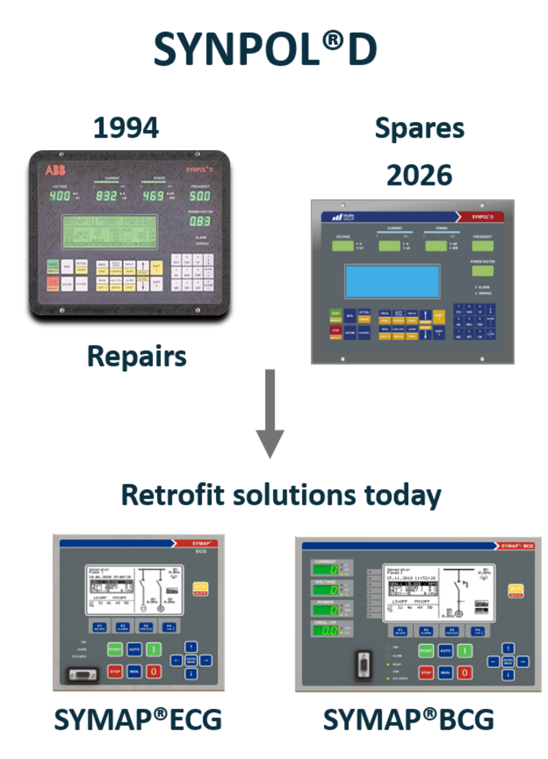
SYNPOL®D offers protection and control as well as Power Management for generators and diesel engines in low and medium voltage systems - with proven lifecycle support for more than 30 years.
You benefit from a 24/7 lifecycle support with
- availability of spare parts
- repair service still today
- complete replacement of all units and cables without modifications
- new design of front panel with stuckeGROUP logo
- download of parameter settings form old device and upload to the new one
- 5 years of warranty
- global onboard service and support
| Description | Specification |
|---|---|
| Generator voltage | |
| 100 V or 400-480 V | |
| three-phase 0.2 VA power consumption | |
| Busbar voltage | |
| 100 V or 400-480 V | |
| two-phase 0.1 VA power consumption | |
| Current transformer connection | |
| 1A three-phase | |
| ca. 1 VA by nominal current | |
| Frequency | |
| 40–70 Hz | |
| Power input | |
| 24 VDC +/- 40% | |
| Relay output | |
| 250 V / 0.5 A AC | |
| 250 V / 0.2 A DC | |
| Analog output | |
| +/- 10 V / 10 mA | |
| 0–20 mA / 5 V | |
| 4–20 mA / 5 V | |
| Protection | |
| IP 00 | |
| Dimension basic unit front plate | |
| H=190, W=277, D=240 mm | |
| Assembly | |
| SYNPOL®D control device, horizontal terminal boards, any position | |
- short-circuit protection that remains effective even if the entire supply voltage of the device should fail
- selective disconnection of a faulted generator. Reconnection protection by manual resetting
- three-step overload protection by overcurrent recording
- reverse power protection
- three-step disconnection of non-essential power consuming components in case of overload, underfrequency and overcurrent
- synchronization of the alternator to the busbar
- automatic speed adaptation of the diesel engine to busbar frequency
- under- and overvoltage monitoring
- under- and overfrequency monitoring
- open circuit monitoring of the current transformer circuits
- asymmetrical current protection
- asymmetrical voltage protection
- self-monitoring of supply voltages and of program operation via watchdog function
- active power measuring, including non-sine voltages and currents and especially thyristor loads (output signal +/- 10 V/DC or +/- 20 mA/DC intended for moving coil instrument connection)
- reactive power measuring
- apparent power measuring
- current output 4-20 mA for remote control display
- permanent storage and indication of all release functions
- supply for the undervoltage coil (direct current), supporting the supply in case of short-time voltage drop
- differential protection with current-adaptive tripping characteristic and minimum differential monitoring in case generator is operating at no load
- earth-fault monitoring, including phase recognition and minimum differential monitoring in case a generator is operating at no load
- counter for following data: working hour, kWh (dual counter), KVAr, start and main breaker
- active load regulation with secondary frequency regulation, twice controlling several mains (in case tie circuit breakers are used)
- power factor in combination with voltage control in several networks
- load-free disconnection of the alternator circuit breaker
- asymmetrical load regulation with constant load setpoint
- asymmetrical power factor control with constant setpoint
- start, stop and pre-glow outputs rated for 24 V / 40 A
- galvanic separation of I/O's by opto-couplers
- galvanic separation of 24 V supply to the engine
- external connections on a separate terminal board
- individual programming for each unit by initialization routine
- actual speed measuring either by tacho generator or by pick-ups, including monitoring
- eight programmable wire fault alarm inputs that permit free determination of logic, delay and alarm text displays
- wire break monitoring of start / stop solenoids
- serial interface between several SYNPOL®D units, as well as interface for data transmission and control of external plants (RS 485, RS 422, RS 232)
- parameter setting via laptop
- menu-operated input of all limit values and parameters
- Power Management with multi-master system
- for land stations: rapid-phase-jump relay, fast voltage and frequency detector
The following table shows the device type related protection functions of SYNPOL®D
| ANSI No. | Protection function |
|---|---|
| 2 | time-relay starting or closing – time relay in a switching sequence – see relays 62 and 79 |
| 3 | checking or interlocking relay |
| 12 | overspeed device |
| 14 | underspeed device |
| 21 | distance relay – operation based impedance Z – admittance Y or reactance X |
| 24 | overexcitation relay – inverse, step or definite time function – operation based on V/Hz principle |
| 25 | sync-check relay |
| 25/A | automatic synchronizing relay |
| 26 | apparatus thermal device – general over- or undertemperature – other than 49 |
| 27 | undervoltage relay |
| 32 | power relay |
| 37 | undercurrent or underpower relay |
| 40 | loss of field relay – based on field dc – current measurement or excessive reactive component of reactive current |
| 46 | phase balance/sequence I relay – incurrent phase sequence or unbalance current relay |
| 46N | negative sequence overcurrent |
| 47 | wrong rotating sequence |
| 50 | instantaneous overcurrent relay or rate-of-rise relay |
| 50BF | breaker tripped failure |
| 51 | time overcurrent relay |
| 51G/N | ground overcurrent |
| 51/27R | voltage restrained time overcurrent relay – time overcurrent relay with pick-up adjusted by undervoltage function |
| 55 | power factor relay – operates if pf slips outside operating area |
| 59 | overvoltage relay |
| 59N | ground overvoltage relay |
| 60FL | voltage transformer failure |
| 67 | directional overcurrent relay |
| 81 | frequency relay |
| 86 | lock out relay |
| 87 | differential relay – normally high impedance type |
| 90 | regulating device – voltage regulator |
| 94 | tripping or trip-free |
SYNPOL®D offers via the RS422/RS485 communication port the Modbus protocol in accordance with „Gould Modbus protocol“ Reference guide PI-MBUS-300 Rev. B.
The protocol controls the query and response cycle which takes place between master and slave devices.
The protocol provides for one master and up to 247 slaves on a common line. SYNPOL®D operates as slave within this network and covers the function 1,2,3,6 & 8 of the Modbus protocol.
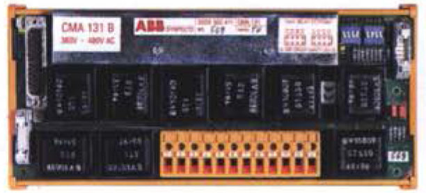
70 × 245 × 109 mm
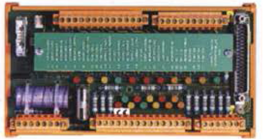
75 × 205 × 109 mm
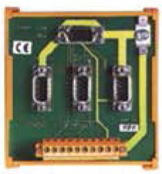
60 × 105 × 109 mm
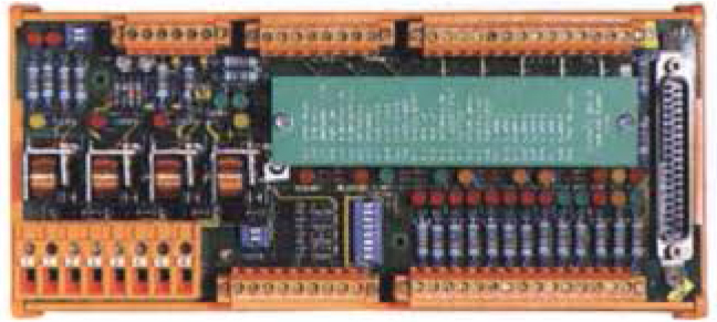
75 × 240 × 109 mm
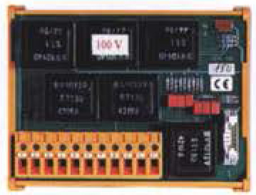
70 × 145 × 109 mm
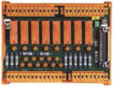
75 × 205 × 109 mm
* Dimensions: height x width x depth
| Terminal board CMA 131 | generator connection with cable A, H |
| Terminal board CMA 132 | generator relay with cable B |
| Terminal board CMA 133 | differential protection and earth-fault monitoring with cable G |
| Terminal board CMA 134 | resistor |
| Terminal board CMA 135 | diesel start, stop, control and monitoring with cable D |
| Terminal board CMA 136 | communication control with cable C |
| Terminal board CMA 137 | additional functions with cable E |
| Terminal board CMA 138 | special types of control |